Floating Drydocks had been around for a long time before World War 2. But the scope of naval warfare during World War 2 and the Cold War that would follow would test the Navy’s ability to maintain vessels in faraway locations. This is part on of the story of docks like USS Los Alamos (AFDB 7) which serviced the Polaris and Poseidon Missile submarines of the Cold War.
Looking back on the years since the LA was placed out of commission, its easy to forget that for over thirty years she served on the front lines of a different kind of conflict. But it was a need identified and filled many years before that which made her ability to fill this new role possible. This is the story of the Floating Drydocks of World War II.

“The fleet of floating drydocks built by the Bureau of Yards and Docks during World War II was a significant and at times dramatic factor in the Navy’s success in waging global war.
It had long been recognized that in the event of another world war the fleet would be required to operate in remote waters, and that ships were going to suffer hard usage and serious battle damage. It was obvious that many crippled ships would be lost, or at least would be out of action for months while returning to home ports for repairs, unless mobile floating drydocks could be provided that could trail the fleet wherever it went. It was the Bureau’s responsibility to meet these requirements.
Floating drydocks have been used for overhaul and repair of ships for many years, and many ingenious designs have been devised from time to time. One of the most interesting was the Adamson dock, patented in 1816, which may be considered the prototype of some of the new mobile docks. The Navy apparently built several wooden sectional docks at various navy yards about 1850, but little is known of their history.
About 1900, two new steel floating drydocks were built for the Navy. The first of these, of 18,000 tons lifting capacity, was built in 1899-1902 at Sparrow’s Point, Md., and towed to the Naval Station a Algiers, La., where it was kept in intermittent service for many years. In 1940, it was towed via the Panama Canal to Pearl Harbor to supplement the inadequate docking facilities there. Since the dock was wider than the Canal locks, it was necessary to disassemble it at Cristobal and to reassemble it at Balboa. Although both the dock and the ship in it were damaged during the Japanese attack on Pearl Harbor on December 7, 1941, the dock was not lost, but was quickly repaired and subsequently performed invaluable service both in the salvaging of vessels damaged in that attack and in the support of the fleet in the Pacific.
The other dock, the Dewey, was a 16,000-ton dock, built in three sections, and capable of docking itself. It was constructed in 1903-1905, also at Sparrow’s Point, Md., and was towed via the Suez Canal to the Philippines. The saga of this voyage is an epic of ocean towing history. The Dewey was still in service at Olongapo when the Japanese invaded the Philippines early in 1942. [sic: Preliminary landings took place as early as 8 December, with the main landings following on the 21st. Manila was occupied on New Years Day. — HyperWar] It was scuttled by the American naval forces before they abandoned the station.
Neither of these docks was suitable for mobile operation. Between 1920 and 1930, the Bureau of Yards and Docks made numerous studies of various types of mobile docks of both unit and sectional types. In 1933, funds were finally obtained for one 2,200-ton dock, and the Bureau designed and built the ARD-1. This dock was of revolutionary design. It was a one-piece dock, ship-shaped in form, with a molded closed bow and a faired stern, and may be best described as U-shaped in both plan and cross-section. The stern was closed by a bottom-hinged flap gate, operated by hydraulic rams. This gate was lowered to permit entrance of a ship into the submerged dock and then closed. The dock was then raised by pumping water from the ballast compartments and also from the main basin. This dock was equipped with its own diesel-electric power plant, pumping plant, repair shops, and crew’s accommodations. It was the first drydock in any navy which was sufficiently self-sustaining to accompany a fleet into remote waters.
The ARD-1 was towed to Pearl Harbor, where it was used successfully throughout the war. Thirty docks of this type, somewhat larger and incorporating many improvements adopted as a result of operational experience with this experimental dock, were constructed and deployed throughout the world during the war.
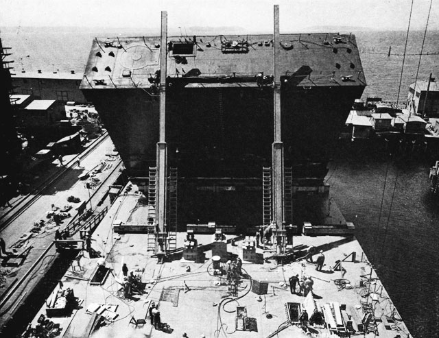
View shows keel blocks and bilge blocks set to accommodate a ship.
In 1935, the Bureau obtained $10,000,000 for a similar one-piece mobile dock, to be capable of lifting any naval vessel afloat. Complete plans and specifications were prepared by the Bureau for this dock, which was to be 1,027 feet long, 165 feet beam, and 75 feet molded depth. Bids received for this huge drydock, designed as the ARD-3, appreciably exceeded the appropriation, and the project was abandoned when the additional funds needed for its execution were refused.
At the same time, plans were prepared for the ARD-2, an improved and enlarged model of the ARD-1. It was not until November 1940, however, that funds were obtained for its construction, and the project placed under contract. The ARD-2, and an additional dock, the ARD-5, were completed in the spring of 1942. Additional docks of this type were built in rapid succession and were delivered during 1943 and 1944 at an average rate of more than one a month.
Types of Floating Drydocks
The war program of floating drydocks included a wide variety of types to meet the varying service requirements for which they were designed. The principal categories were as follows:
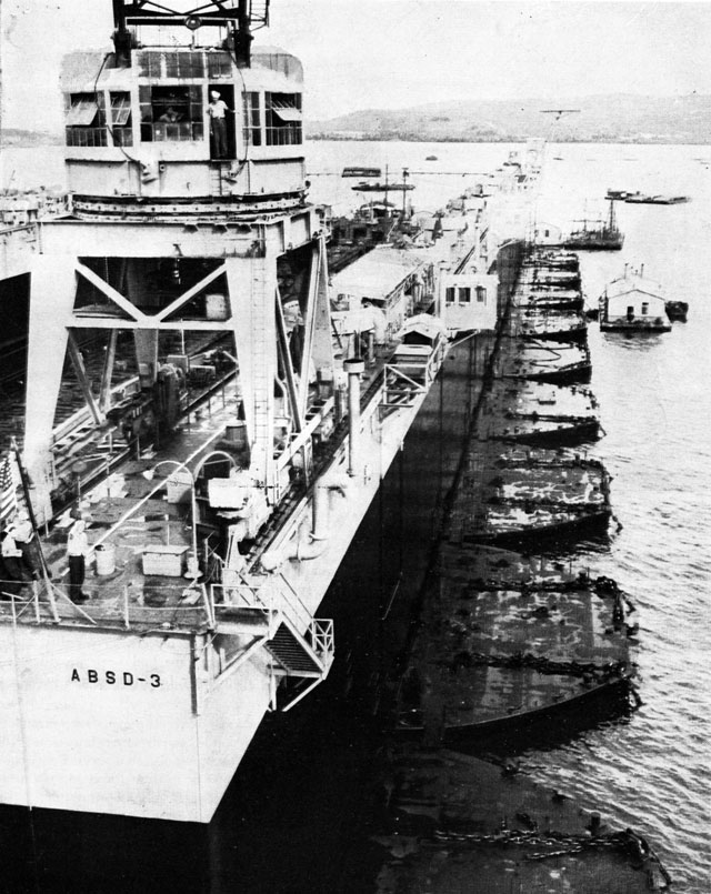
- ABSD — Advance Base Sectional Dock. Mobile, military, steel dock, either (a) of ten sections of 10,000 tons lifting capacity each, or (b) of seven sections of 8,000 tons lifting capacity, for battleships, carriers, cruisers, and large auxiliaries.
- ARD — Auxiliary Repair Dock. Mobile, military, steel unit dock, ship-form hull, with a normal lifting capacity of 3,500 tons, for destroyers, submarines, and small auxiliaries.
- ARDC — Auxiliary Repair Dock, Concrete. Mobile, military concrete trough type, unit dock with faired bow and stern, 2,800 tons lifting capacity.
- AFD — Auxiliary Floating Dock. Mobile, military, steel trough type, unit dock, with faired bow and stern, of 1,000 tons lifting capacity.
- AFDL — Auxiliary Floating Dock, Lengthened. Mobile, steel trough type, unit dock, similar to AFD’s, but lengthened and enlarged to provide 1,900 tons lifting capacity.
- YFD — Yard Floating Dock. This category included a wide variety of types, designed generally for yard or harbor use, with services supplied from shore. Among the principal types were 400-ton concrete trough docks; 1,000-ton, 3,000-ton and 5,000-ton one-piece timber trough docks; sectional timber docks ranging from 7,000 to 20,000 tons lifting capacity; and three-piece self-docking steel sectional docks of 14,000 to 18,000 tons lifting capacity.
These classifications were modified in 1946 in order to make the standard nomenclature of floating drydocks consistent and more descriptive. Four class designations were established, as follows:
- AFDB — Auxiliary Floating Drydock Big.30,000 tons and larger.
- AFDM — Auxiliary Floating Drydock Medium.10,000 to 30,000 tons.
- AFDL — Auxiliary Floating Drydock Little. Less than 10,000 tons.
- AFDL(C) — Auxiliary Floating Drydock Little (Concrete).
Under this modification, the ABSD’s were redesignated AFDB’s; the ARD’s became AFDU’s; the RDC’s became AFDL(C)’s; the AFD’s became AFDL’s; and the YFD’s became AFDM’s.
Advance Base Sectional Dock
The problem of providing floating drydocks capable of moving to advanced operational areas in the wake of the fleet, of sustaining themselves in full operation without support from shore, and of sufficient size and lifting capacity to dock all capital ships had been under study by the Bureau for many years. The ARD-3 was one solution of this problem. It was recognized that a unit dock of this size possessed certain disadvantages. In required a special basin of huge size for its initial construction. It was necessary to retain this basin in reserve or provide an equivalent basin elsewhere, for the periodic docking of the hull, since it was not self-docking. The towing of a craft of this size presented an operational problem of unprecedented magnitude. Provision for stresses during storms at sea required heavy reinforcement of the dock. Concern was felt over the possibility of losing the unit dock from enemy action while en route.

Showing the ship secured in position so that it will be supported on the prepared blocking as the dock is unwatered.
Studies had been carried on concurrently by the Bureau on various types of sectional docks, which would be designed with faired hulls for ease of towing and with joint details which would permit rapid assembly in forward areas under adverse conditions. These schemes were not carried to a final conclusion, primarily because the requirements of the Bureau of Ships for the longitudinal strength and stiffness of the assembled dock could not be met by an practicable form of joint.
When war was declared, it was apparent at once that a number of mobile capital-ship floating drydocks would have to be constructed immediately. The project was authorized and funds made available early in 1942. Studies in connection with the preparation of plans and specifications led to the proposal of a sectional type of dock, with field-welded joints, designed for a strength materially below that previously specified by the Bureau of Ships. This reduction was accepted, and the sectional type adopted.
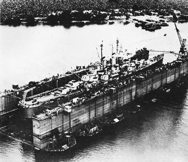
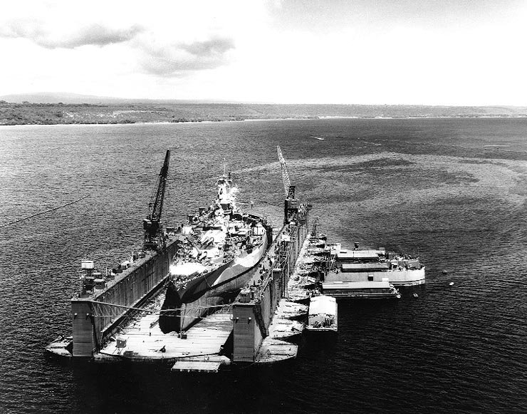
Water is pumped out of the bottom pontoons and wingwall compartments to raise the ship out of the water.
These docks were of two different sizes. For battleships, carriers, and the largest auxiliaries, the larger docks, consisted of ten section, each 256 feet long and 80 feet wide, and with a nominal lifting capacity of 10,000 tons. When assembled to form the dock, these sections were placed transversely with 50-foot outrigger platforms at either end of the assembly, making the dock 927 feet long and 256 feet wide overall, with an effective length of 827 feet, a clear width inside wing walls of 133 feet, and a lifting capacity of 90,000 tons.
The smaller docks, intended for all except the largest battleships, carriers, and auxiliaries, consisted of seven sections, each 240 feet long and 101 feet wide, with a lifting capacity of 8,000 tons. The assembled dock had an effective length of 725 feet, an overall length of 825 feet, a width of 240 feet, a clear width inside wing walls of 120 feet, and a lifting capacity of 55,000 tons.
At maximum submergence the 10-section docks had a depth over the blocks of 46 feet, with a freeboard of almost 6 feet; the 7-section docks had a corresponding depth of 40 feet and and a freeboard of almost 5 feet.
For both sizes, the sections were faired fore and aft to a truncated bow and stern, and could be towed at a speed of 6 to 8 knots without excessive power. In the assembled docks, the flat bows and sterns formed interrupted berths alongside to which barges and vessels could be readily moored.
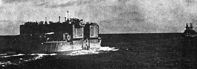
A Section of an Advance Base Sectional Dock in Tow
Wingwalls are down to reduce wind resistance. Repair equipment is stowed on deck.
The sections consisted of the bottom pontoon and two wing walls, which were hinged at the bottom so that they could be folded inboard for towing, the purpose being to reduce the presentation to the wind and to lower the center of gravity as compared to fixed standing wing walls.
Each bottom pontoon of the battleship dock was 28 feet deep and was subdivided by two watertight bulkheads running lengthwise and four watertight bulkheads athwart the section to form twelve water ballast compartments and a central buoyancy compartment, 36 feet by 80 feet. This buoyancy compartment contained two decks, the upper deck being used for crew’s quarters, and the lower deck, for the machinery compartment. The double bottom was subdivided to form fuel-oil and fresh water tanks. Access to the usable compartments was provided by passageways under the upper pontoon deck which connected to stair trunks in the wing walls.
The wing walls were 20 feet wide and 55 feet high, and were subdivided by a safety deck set 14 feet below the top deck to form dry compartments above and three water ballast compartments below. The dry compartments were completely utilized for shops, storage, and similar facilities. Quarters and galleys were in the dry compartments in the bottom pontoons.
Each section was equipped with two 525-h.p. diesel engines directly connected to 350-k.w. generators, and with pumps evaporators, compressors, and heating and ventilating apparatus. No propulsion machinery was provided.
The smaller docks were similar, except that the bottom pontoons were 231/2 feet deep and the wing walls were 18 feet wide and 49 feet high.
Each dock was equipped with two portal jib cranes having a lifting capacity of 15 tons at a radius of 85 feet, traveling on rails on the top deck of the wing walls. In the case of the smaller dock, the cranes were set back from the inner face of the wing walls to provide clearance for overhanging superstructures of carriers, and the outer rail was supported on steel framing erected on the outboard portion of the pontoon deck.
ABSD Construction
The 58 sections required for these docks were constructed by five contractors at six different sites, including four on the West Coast, one on the Gulf Coast, and one near Pittsburgh on the Ohio River. Generally, they were built in dry excavated basins which were flooded and opened to the harbor for launching. In one case, two basins in tandem were utilized to suit local site conditions, and the sections were locked down from the upper basin, in which they were built, to the lower basin, the water level of which was normally at tide level and was raised temporarily by pumping.
Picture:
Raising the Wingwalls of an Advance Base Sectional Dock with Hydraulic Jacks
Crews on top of wingwalls change position of the pins in the beams alternatively.
At one yard, the sections were built on inclined shipways and end-launched; at another, they were side-launched. These sections were built in from 8 to 14 months. Maximum possible use was made of prefabrication and pre-assembly methods.
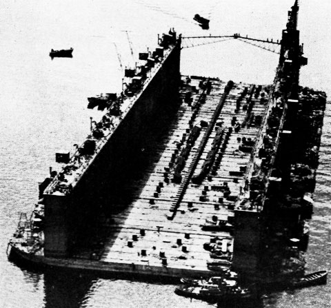
ABSD Assembly. — Although the wing walls were generally erected initially in their upright position for ease of construction, it was necessary to lower them to the horizontal position for towing at sea. On arrival at the advance base where they were to be placed in service, the wing walls were first raised again to their normal position and the sections then aligned and connected.
An ingenious method was evolved for the raising of the wing walls, which was found to be quicker and more certain than the scheme originally contemplated of accomplishing the result by the buoyancy process. Each wing wall was jacked into position, using two jacking assemblies, each consisting of a long telescoping box strut and a 500-ton hydraulic jack. Closely spaced matching holes were provided in the outer and inner boxes of the strut through which pins were inserted to permit holding the load while the jacks were run back after reaching the limit of their travel. These devices were also designed to hold back the weight of the wing walls after they passed the balance point during the raising operation. Two 100-ton jacks opposing the main jacks were used for this purpose. After the wing walls were in the vertical position, they were bolted to the bottom pontoon around their entire perimeter, and all access connection between the wing wall and bottom pontoon were made watertight.
The sections of each dock were successively brought together and aligned by means of the matching pintles and gudgeons which had been provided for the purpose on the meeting faces of the sections. Heavy splice plates were then welded in position from section to section across the joints at the wing walls, at top and bottom, and on both the inside and the outside faces of the wing walls. The strength of these connections gave the assembled dock a resisting moment of about 500,000 foot-tons, or approximately one-fourth that of the largest prospective vessel to be docked.
The drydock cranes were carried on the pontoon deck of individual sections during tow, and were shifted to their operating position on the wing walls during assembly of the dock by immerging the partially assembled dock, bringing the section carrying the crane alongside, and aligning it so the rails on the pontoon deck were in line with those on the wing walls of the rest of the dock. The trim and alignment were adjusted during the transfer by a delicate control of water ballast.
The assembled docks were moored at anchorages in protected harbors where wave conditions, depth of water, and bottom holding power were satisfactory. The large docks required at least 80 feet depth for effective use. They were moored by 32 fifteen-ton anchors, 14 on both side and 2 at either end, with 150 fathoms scope of chain.
In actual operation, it was found that the effectiveness of these docks could be improved by providing auxiliary facilities in excess of those available on the dock itself. A considerable number of shop, storage, and personnel accommodation barges were provided for this purpose.
Special Problems
Special conditions of service involved many entirely new studies and developments for our floating drydocks. For instance, as the docks had to operate in outlying areas where ideal conditions for operation could not always be met, it was necessary to give the adequacy of their moorings special consideration. In the largest size docks, this involved wind-tunnel experiments which gave some surprising results and indicated that a rearrangement of the moorings as originally planned was desirable. Also, as the drydock operating crews were initially relatively inexperienced and docking of ships under advance base conditions had never been attempted to the extent contemplated, it was necessary to prepare complete operating manuals for the use and guidance of the crews. Damage control was also important, and damage-control manuals were prepared for all advance base docks, covering every possible contingency of weather an enemy action.
As advance base docks were commissioned and had regular Navy crews and as they operated in areas where they had to be self-sustaining to a large extent, it was necessary to develop allowance lists for each type of dock and outfit them in much the same manner as a ship. This necessitated the incorporation into the docks of special facilities for the handling, stowage, and issuance of great quantities of material and equipment.
Complete statistics have not been compiled of the total number of vessels of all kinds from the mightiest battleship and carriers to the humblest patrol craft that were salvaged, repaired, and overhauled in this armada of floating drydocks. Themost dramatic demonstration of the importance of the mobile drydocks was given during the long drawn-out naval support of the invasion of Okinawa, when the fleet was subjected for weeks to continual and desperate “Kamikaze” attacks by Japanese suicide-bombers. The fleet suffered great damage, but the ready availability of the mobile drydocks at nearby advance bases, and the yeoman service rendered by their own crews and the ship repair components at these bases, save many ships and minimized the time ships were out of action for repairs, to such an extent that these docks may well have represented the margin between success and failure.”
The AFDB’s served on for many years. You can read about some of their stories in the archives of theleansubmariner.com

Mister MAC, you keep coming up with these great article that are so dear to me.
As you know, I was one of the Seabees that helped erect the AFDB-7 LOS ALAMOS floating drydock in Holy Loch, Scotland in 1961.
I have a 2″ note book full of information and documentation about it, but you have filled in more of the history of their past that I ever thought would be available to anyone.
I appreciate all the work you have done to document the proud history of the dry-docks and especially the AFDB-7 Los Alamos and for including my story about it, “IN THE BEGINNING” on your blog.
Thank you.
Norman Rachels
Honorary Crew Member
AFDB-7 Los Alamos
since 27 September 1983
Always honored when you connect Norm. I hope the memories we have will live for another age. People forget all of the sacrifices that were made in a number of corners of the world to protect freedom.
Reblogged this on TonyShook and commented:
A fascinating look at an often overlooked part of naval history. Little glory in their work, but without this kind of support, the battles in distant waters during WW II would have had a very different outcome. BZ, Mister Mac.
Once again Mister Mac, you show aspects of our history that most have overlooked. Having been on several boats that obtained services from these behemoths I have some appreciation of the work they did. This look into the history of them was both enlightening and a source of pride for this former sailor.
Thanks Tony. The Docks were pretty important to me personally but I am glad that their story will get another chance to be told. I really appreciate the feedback
Mac
Reblogged this on Tales of an Asia Sailor.
The days spent in the floating drydock in Rota, Spain (1965-70) while serving aboard USS Lafayette, SSBN-616 were memorable. She went into drydock before my first patrol as an MM-3 and I left her drydock five years later as an MM-1(SS). Few submariners have the opportunity to see their first ship from top to bottom, other than new construction.